Week 15: Networking and Communications
On Wednesday 11/05/16 we had a very interesting local review where everyone showed the results of their composite week. Later Neil spoke about networking and ways of making devices communicate between them. One of my first questions which was to understand the reason why I would want to do that, was answered right away:
- Distance / Location: To enable communication between two parties separated by physical distance
- Paralellism: To split the system into two processors doing different jobs
- Modularity: To be able to test and debug independently
- Intereference: To prevent interference from one element to the other
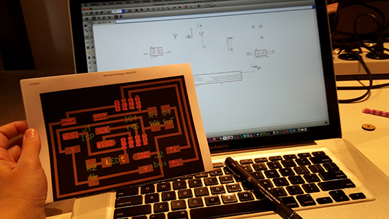
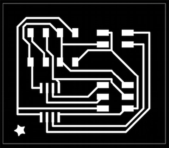
Thursday 12/05/16 We also had an interesting local lesson with Emma who went though some of Neil's examples in more detail. I had to make a desicion of which network to make. For my final project I really don't need a network although Emma suggested that I could maybe connect my chair to a mobile phone through bluetooth. I had a think and I decided to go for a simple example, since I still have a lot to learn about circuits, Eagle etc. I also could not find solid reasoning as to why connecting my chair to bluetooth would benefit my project. In the end I started with Neil's 'Asynchronous Communication' example because it seemed simple enough to allow me to concentrate on things that I wanted to explore further. This time I decided to design from board to schematic. It was already a challenge for me…
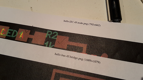
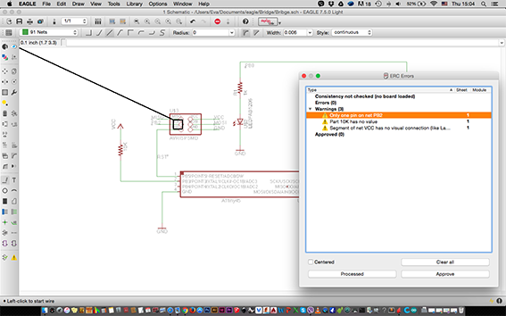
After struggling a little bit on my own, I asked for Emma's assistance, who helped me understand how the routes work. We also went through the schematic in relation to the board in a little more detail which was very helpful. I now have a more solid understanding of how to make schematics - and how to connect elements to each other. The problem in this case was an unexpected one… As I prefer to work from a printed paper so I can take notes and have the whole picture in front of me, I had printed a bridge from the 'bus' example and a node from the 'I2C' example! Thankfully Emma spotted that quite early so I was able to finish my schematics and proceed to the errors inspection. To my satisfaction I could understand what the errors were saying and I was already content with my decision to go for the simple example! As I eliminated all errors, I got a confirmation from Emma that everything was fine and I proceeded to autoroute my boards.
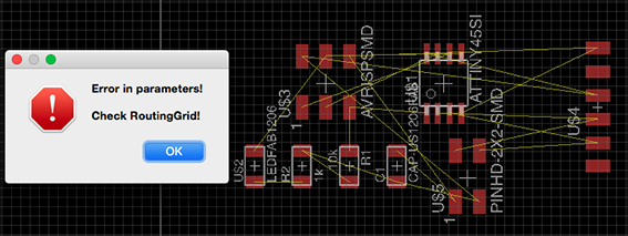
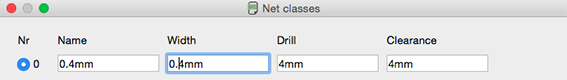
On Friday 13/05/16 I found myself facing an issue with autorouting since Eagle was showing me a warning that I couldn't understand. I did some reading and I undrestood the importance of using 'Ratsnest', which automaticaly switches to the simplest airwire connection between the elements. After visiting many forums where people seem to be plainly exlpaining their own point of view rather than what you are asking, I figured out that the routing grid was different to the grid on which we are designing and that is set in the Net Classes!! That was my mistake! I had set everything to 4mm instead of 0,4mm and that was why it was refusing to make the routes for me.
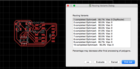

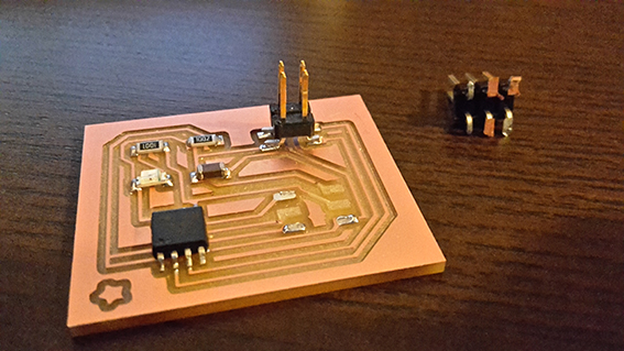
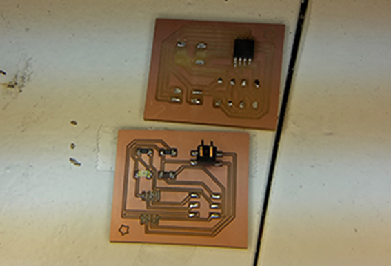
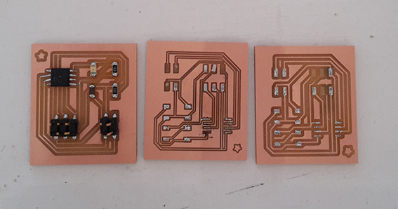
By then I was already feeling more confident about my use of Eagle, but I reached a point where the autorouting would not produce a 100% option for the bridge. After moving the parts around a little bit more and looking into Neil's board I was able to have two boards ready for milling! I have to admit that this process was a lot faster than it would have been ten weeks ago!
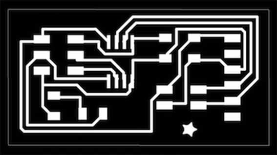
I had two boards ready for milling in less than one day!
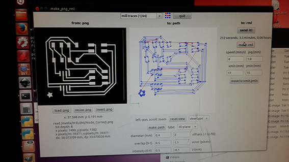
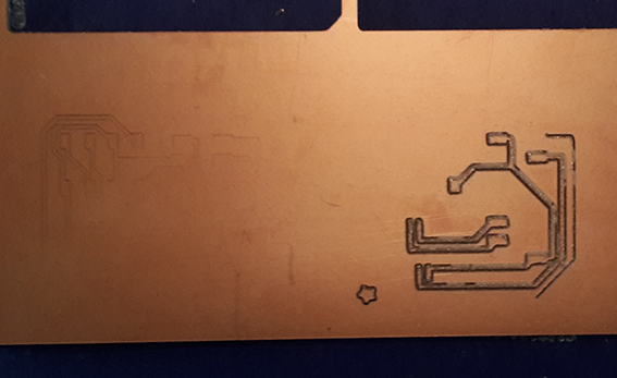
Milling was a pretty straightforward operation although the endmill seemed to be a little blunt and it stopped halfway through the job. I replaced it with a new one and stuffed the two boards. This became such a usual thing to do that I don't have photos of gathering the components on my piece of paper, naming them so I don't lose them or even soldering!
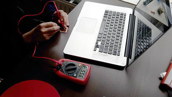
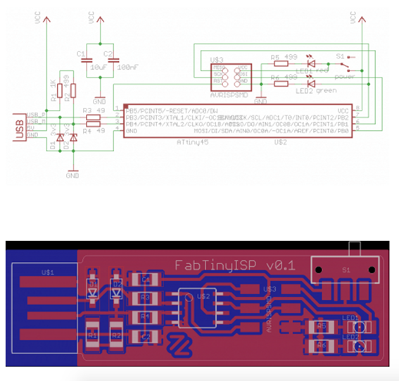
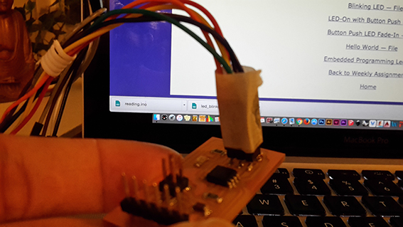
Saturday 14/05/16 I checked my two boards with the multimeter at home and was happy that I didn't have any issues (and I knew how to check for those issues!). It was time to check whether the software side of things was in operating mode too. I realised that I couldn't simply use my standard connector to connect the ISP to the boards because the pinout was different and I was looking for a way to figure out Zaerc's pinout since I couldn't find any of his Eagle designs. In the end I realised that I only needed to know one pin in order to figure the rest of them out from the schematic image! I am now interpreting schematics!
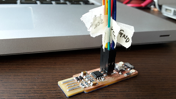
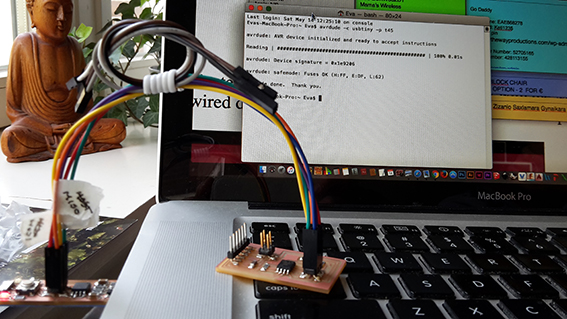
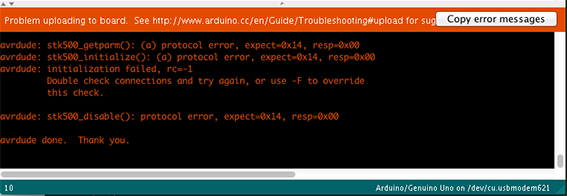
I used some female connectors that I bought and carefully connected them to the ISP easily getting a positive message from both boards after running the 'avrdude -c usbtiny -p t45' command! Then I left for dinner which was probably not a very good idea because I lost my concentration! Before leaving, I disconneced my wires and when I put them back on the bridge board and ran the avrdude command again, I was getting a message to check my connections.
Clever me, I had taped the female connectors together this time, so that I wouldn't lose the orientation of the cables and I decided to pull them out all together. By doing that I pulled the whole connector out with the copper pads still stuck on it and damaged my board. I was very upset with myself because I thought I was going to spend the rest of the long weekend programming… Monday is a public holiday in The Netherlands and I didn't want to ask Emma to open the FabLab just for me, although she offered to.
I had to get over my frustration and proceed with the node on which I succeded to burn the bootloader and then load a simple blinking led code, just to make sure that everything is fine.
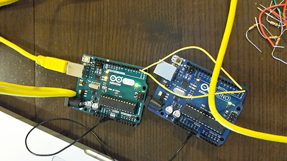
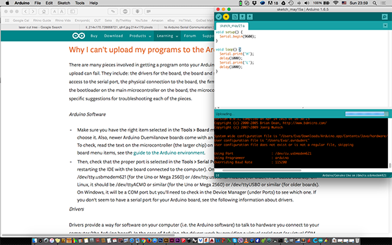
On Sunday 15/05/16 I did some reading from previous years' projects but I can't say that I found much help. I read Aditi Gupta's entry as well as Dana Schwimmer's but they did not seem to be of much assistance to what I want to do. At the moment it is a puzzle to me how the two boards will 'talk to each other' or exactly what to expect from this sentence! I understood that I have to connect the RX of one board to the TX of the other and vice versa, but I have actually never seen anyone doing this - not even a video. Since one of my boards was destroyed I attempted to follow this tutorial to connect two Arduinos together. It has been almost two hours and the code is still being loaded on one of them!
I eventually stopped it, because it seemed to be going nowhere.
In the end, on Monday 16/05/16 I did ask Emma to open the FabLab so I could re-do the board that I messed up. This was indeed pretty straightforward, as I just removed the components from one board and re-soldered them on the one that I had milled as a spare. It went smoothly and I succesfully ran the avrdude command and proceeded to burn the bootloader.
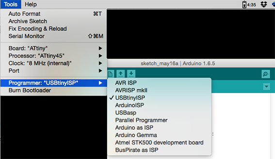
Emma also explained to me that to create asychronous communication between the microcontrollers in the Arduino IDE would be very tricky and she suggested that I proceed with using Neil's 'C' code from the student archive. Unidentified waters once again! Thankfully she also pointed me out to Anna Kaziuna's tutorial which appears to be very clear. This was very helpful, because I spent a lot of time searching and reading about networking, but I couldn't find answers that suited my case. I couldn't understand exactly how this would happen. Most of the texts I read were not even completely related to what I wanted to do, so I will not even bother with listing them here.
On Tuesday 17/05/16 I started to follow the tutorial I mention above as well as the one from Embedded Electronics week which you can find here . In the mean time I managed to pull out the pads of my node once again so I had to mill and re-solder another board. This is caused by the new way I am using to solder the components. I first I put solder on all pads of a specific component and then I heat it up with the heat-gun, steadily holding the component in place. I just need to be adding more solder on top sometimes, especially on connectors who get a lot of strain. Making a third board, to my suprise took a very little time. (milling and stuffing a board seems to have become a small parenthesis in my day, it seems!). I continued with the tutorials.
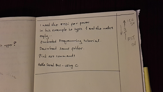
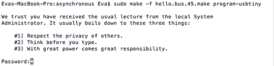
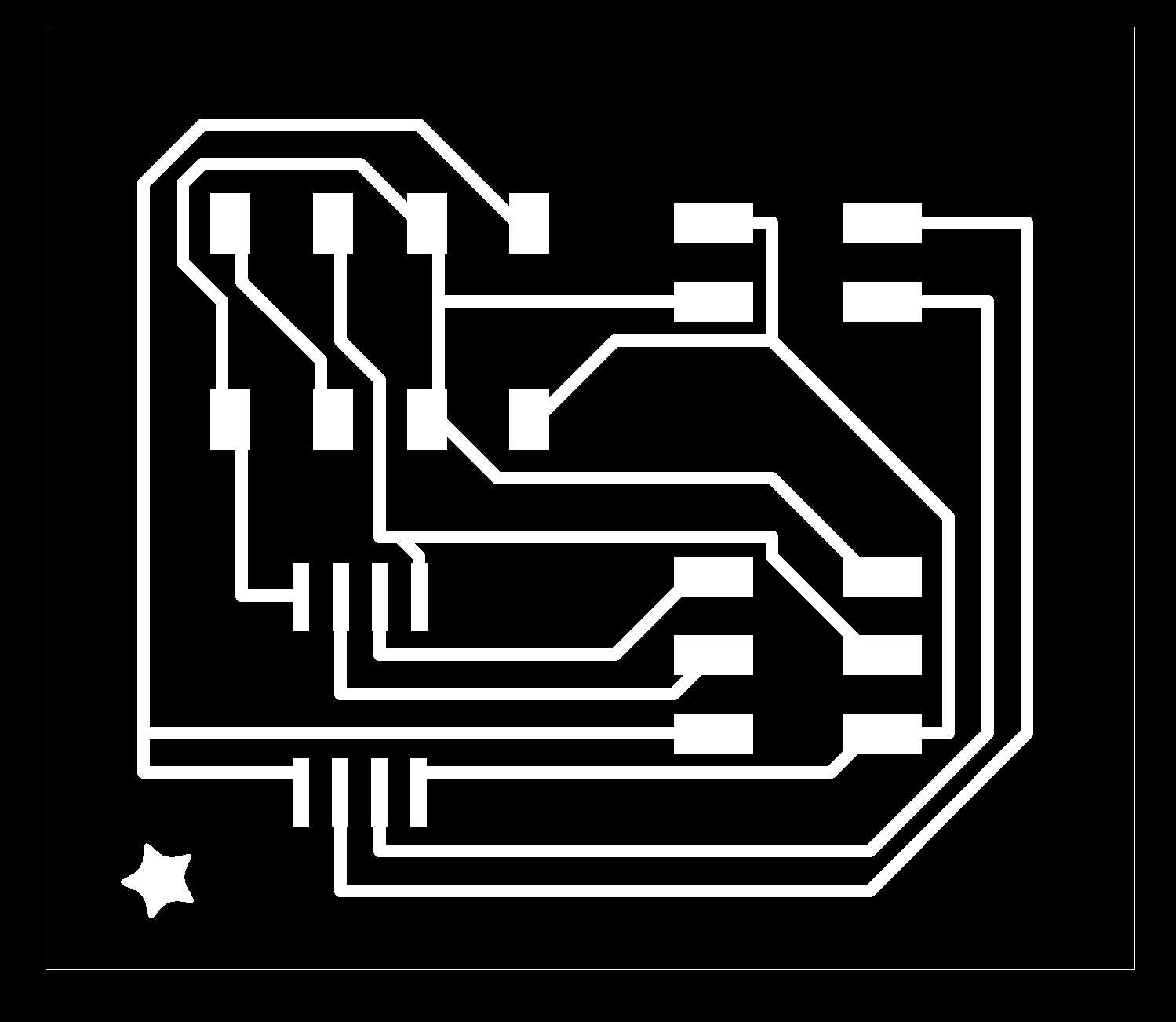
I first connected my ISP to the bridge and I downloaded the hello.bus.45.c and makefile by right clicking on them and selecting 'Save Link As' while in Google Chrome. If I tried to copy and paste them in another application I would get another extension and I didn't want that. I created a new folder and saved them in it together. I then opened the terminal window (I am a mac user) and navigated to that folder. From there I typed '$ make -f hello.bus.45.make' to extract a .hex and .out file, which are necessary for communication and I ran the '$ sudo make -f hello.bus.45.make program-usbtiny' command. This programmed the bridge with Neil's 'C' code.
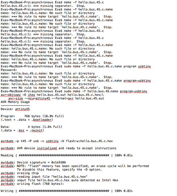
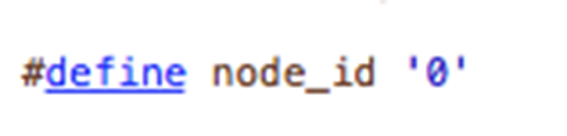
I proceeded to program the node. I opened Neil's 'c' code with Xcode and I changed the #define node_id '0' to #define node_id '1'. I connected it to the ISP again and I tried all of the commands that you see above until the last one finally worked! The mistakes I had been doing were that I did not realize which part of the command line was the actual command, which was the filename and which the extension of the file. As it turns out 'make -f' is the command '.make' is an extension and the part between them is the actual name of the file. In the case of '$ sudo make -f hello.bus.45.make program-usbtiny', 'sudo make -f' is the command, followed by the file name and program-usbtiny at the end. This was a bit tricky to understand as the only programming and networking knowledge I have came from my very few months in the Fab Academy. On top of that the tutorial was talking about files that someone else had named. All is well that ends well, as the saying goes and at least I now know what was going wrong.
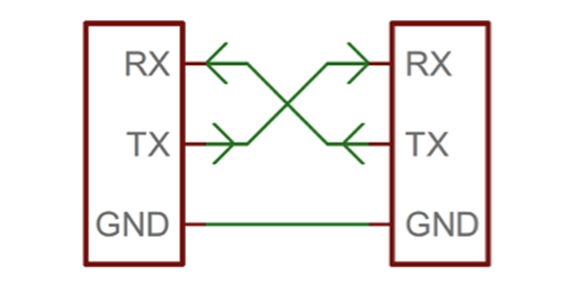
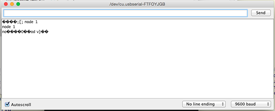
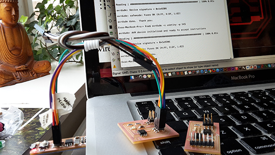
I continued by connecting the boards between them as the image above shows. I connected the bridge to the FTDI cable and I opened the Arduino IDE and the serial monitor. At first it seemed not to recognise what I was doing, but I of course had to select the USB port for communication. Once did that, I typed the number and it responded with a 'Node1' message! I had communication. The communication is not always flawless because the boards have no resonator so I sometimes get some questionmarks instead of a clear… answer. I am definitely happy that I have completed yet another assignment successfully.Looking back, I am sorry that I did not make more nodes so that I could have more of them connected. Who knows, I might make one now that have become faster at milling and stuffing!
I also found the following quite funny and worthy to include on the website!
* Until this point I unfortunately do not have a video of the LED's blinking while the nodes are communicating. I attempted to record one, but I mistakenly crossed the VCC and GND wires which burned the microcontroller. I have replaced it and re-programmed, but at the moment the boards are not communicating. I am in the process of debugging, but also in the process of completing next week's assignment and the beginning of the final project.
Bridge - Schematic Bridge - Board Bridge - PNG Traces Bridge - PNG Border Node - Schematic Node - Board Node - PNG Traces Node - PNG Border Networking and Communications Lecture Back to Weekly Assignments Home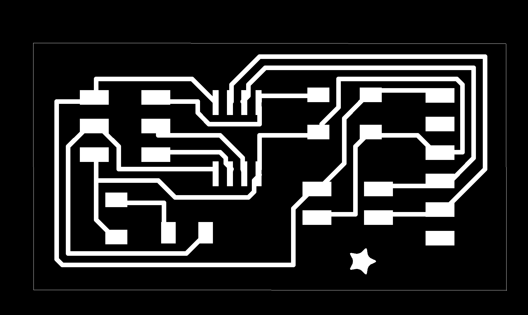